PC Based Data Acquisition and Control System |
Mike is responsible for development of Data Acquisition and Control (DA&C) systems at Northrop Grumman’s Capistrano Test Site (CTS). The DA&C systems are used to test and validate rocket engines and military-grade chemical lasers. In addition to the acquisition and control requirements, these systems must protect life, environment, and NGC property from the extreme temperature, pressure, and chemical hazards associated with CTS test facilities.
The world-class system delivered in May of 2009 utilizes small form factor PC/104 embedded computers and I/O boards to interface with site facilities. The system will forever be known as the “PC/104 System” despite several failed attempts at a better handle. The current configuration monitors and controls over 500 AI, DI, DO, and DAC channels in real-time at 125 and 1250Hz rates. Keyboards and touch screens provide user input, while 12 monitors provide real-time displays of converted engineering unit values, plots, and graphic elements.
Several of the engines qualified on this system in 2009 will be aboard the James Web Space Telescope (see photos below).
Note: The DA&C system is not classified. Mike was given permission by NGC Intellectual Asset Management to publish his work. Because some of the test articles are proprietary, names, values, and art work on screen images have been modified or redacted to protect original content. Image resolution has also been reduced.
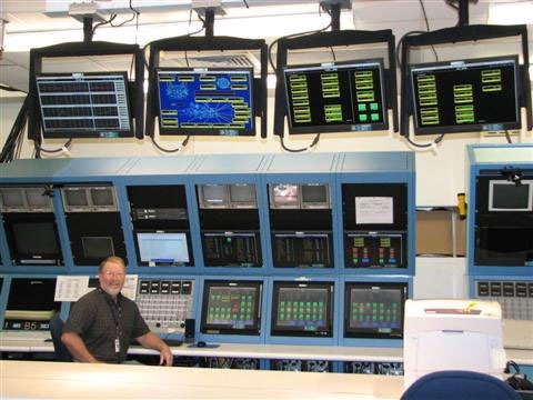
This photo shows Mike at the test operations console keyboard. Touch screens and monitors used to conduct tests are to the right. The monitors hanging from the ceiling are much closer to the camera. They display real-time data for our customers.
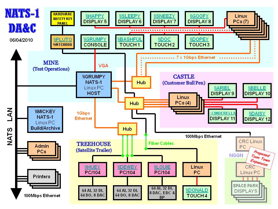
The PC/104 system is composed of 15 PC’s running multi-threaded Linux applications. They communicate via Ethernet.
Three major areas are shaded in the diagram. Test Operations functionality (Mine), shaded light blue, provides user interfaces and safety hardware should the watchdog take over during a test. The magenta area contains displays for the customers (Castle). The satellite functionality (Tree House) in the beige area is located remotely in a trailer near the test call. It contains the PC/104 units and all necessary interfaces to test stand facilities (amplifiers, analog filters, relays, valve drivers, thermocouples, and transducers).
A “Host” server, running dozens of multi-threaded processes ties the system together. Multiple Ethernet ports on the server connect to the display clients. The server uses a combination of shared memory, messaging queues, and semaphores to coordinate simultaneous tasks: PC/104 connection, incoming raw data, engineering unit conversion, calculations, data logging, user input, console output, command logging, timeline processing, display connection, display updates, report generation, configuration database handler, configuration dictionary, software watchdog, hardware watchdog handler, third-party I/O hardware handlers, audio handler, hardware safety panel handler, data archiving, configuration validation, configuration archiving, and system health monitoring.
Note on Naming: Mike inherited a private LAN with 75+ randomly named systems spread through multiple buildings stretching a mile across the hillside. Given the number of names needed, J.R.R. Tolkien books were the best resource. New identities were assigned using logical groups of hobbits, men, elves, dwarves, wizards, and places. The printer in the nicest place was named RIVENDELL, the darkest became MIRKWOOD. The oldest system: TREEBEARD. The first to be eliminated: BOROMIR. Remaining Tolkien names were too obscure to remember for the PC/104 system. Mike switched to Disney characters. The names make for great email descriptions of problems.
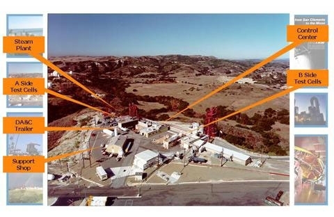
The PC/104 system is deployed at the High Energy Propellant Test Stand (HEPTS). Many of the following slides were originally presented by Mike to the Rocket Test Group (previously RTFOWG) conference at Kennedy Space Center.
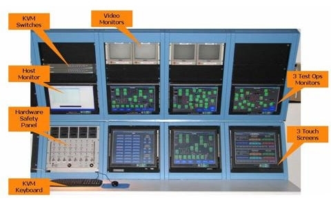
Test Operations Console
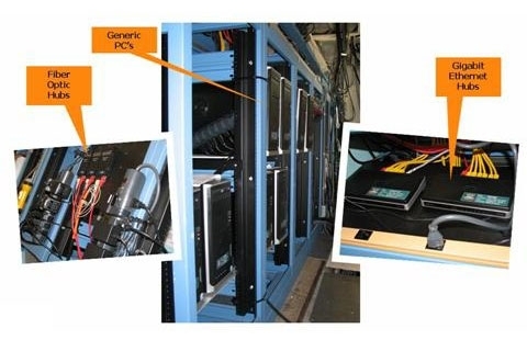
All system components in the control center are inexpensive, commercially available hardware.
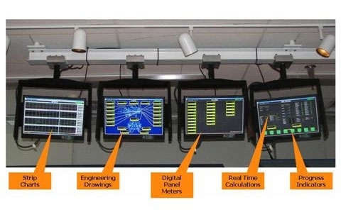
One of the extra skills Mike brought from GTE and HP is a focus on customer needs. One or more engineers from Space Park in Redondo Beach is on site for every test. Along with giving approval to start tests, they control the abort pickle. This is a button at the end of a cable to manually abort a test and secure the system if there is a significant failure. On past systems, these engineers have looked over the shoulder of test operation personnel to interpret displays designed for operational convenience. The PC/104 system provides 4 monitors that can’t even be seen by operators. These provide real-time data designed to meet the customer needs. Not only are abort values clearly displayed in yellow and red as the approach extremes, but many calculations that were previously available only after test completion are now there in real time. This has significantly cut the necessary analysis time between tests.
The host system monitors all channels every 10 msec for pre-defined abort conditions, so the chances of anyone hitting the pickle first is slim.
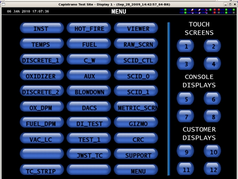
Up to 30 different screen formats are supported in the current system. The main menu screen allows operators to select screen formats on the left, and then the display where they will be sent.
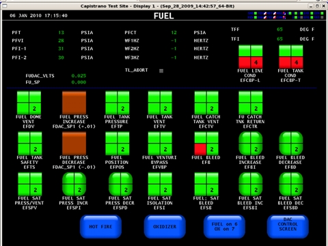
This FUEL system control screen contains discrete values as well as a variety of touch control buttons. Green and red indicate OFF (green or safe) and ON (red). The numbers indicate safety keys (4 is enabled, 2 is disabled). Shape indicates behavior: square-cornered are toggles; round-corner are momentary. The simple brown buttons are momentary buttons for DACs. The large blue ones are shortcuts for keyboard commands.
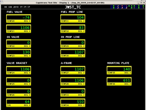
This is a JWST thruster temperature screen containing Digital Panel Meters.
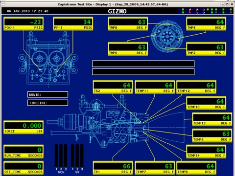
On this screen, DPMs are displayed over an enginering drawing background.
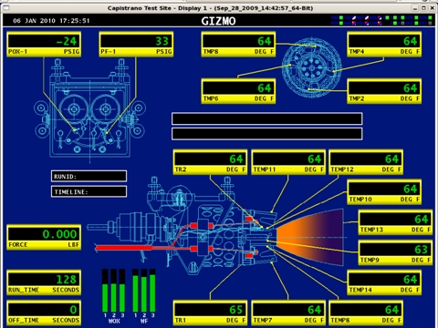
Bit map graphics are over-laid to clearly indicate operational states.
System status is important to know at all times. Typical "modem style" flashing indicators could not contain all the information necessary in an acceptably small screen space. By using a "barber pole" style indicator, 15 different GIF files can be displayed serially in each 8x8 pixel indicator. The resulting animation provides clear status of frequent events such as screen refreshes (5 Hz). Intermittent events like user touch screen input are visable as a single pixel diagonal movement. Simpler conditions such as Ethernet Send Status are represented by GREEN/RED indicators.
This is an animated GIF file simulating a single barber pole as well as a GREEN/RED indicator. These indicators are clear at much faster and much slower speeds.
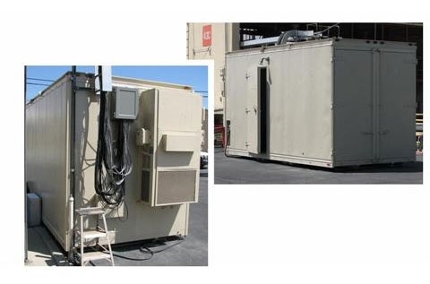
The climate controlled satellite trailer is located close to the test cell. It contains power supplies, signal conditioning equipment, the DA&C satellites, and an additional full-function touch screen.
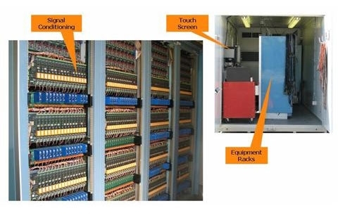
Signal conditioning equipment filters and amplifies incoming analog signals. Valve drivers on the opposite side of this rack boost digital and analog outputs to power various high power facility controls.
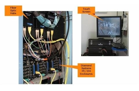
The business end of the DA&C system is the 3 PC/104 satellite enclosures running embedded Linux code developed at CTS. Each of these units handles 64 analog inputs, 32 digital inputs, 32 digital outputs, and 8 digital to analog converters. Most of the inputs are scanned at 100 Hz frequencies. A subset is scanned at 1250 Hz for higher resolution data.
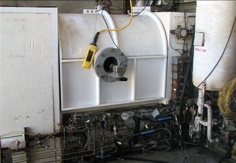
This is the test cell with the lid closed. The small camera pointed in the observation window records all tests on video tape.
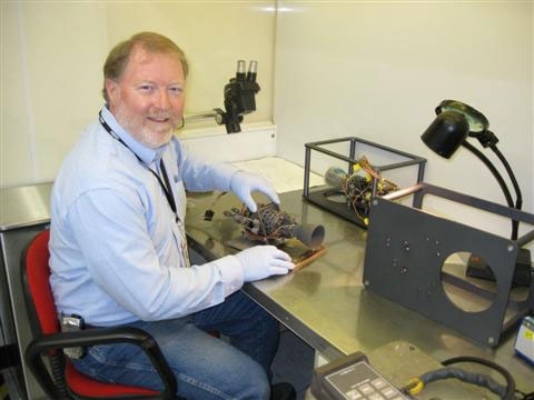
Mike is holding James Webb Space Telescope (JWST) thruster #3. Once the JWST is in close-Earth orbit, this $800K engine will be lit for over 3 hours to accelerate the vehicle to the L2 Lagrange point 1.5 million miles from Earth.
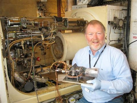
This is JWST #3 immediately after removal from the vacuum cell. That large exhaust pipe behind me is connected to massive vacuum hardware that maintains a 1 torr vacuum throughout the tests. Earth atmosphere at sea level is about 750 torr. Blood and other bodily fluids boil off at 400 torr.
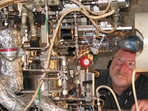
This is a different engine mounted in the test cell. During tests, the hardware supplies fuel and oxidizer, measures thrust, and reads several hundred temperatures and pressures.
Everything in that test cell has to function at very low pressures and high temperatures.
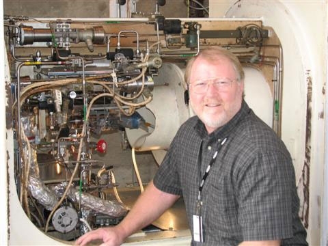
Hard work pays off.
Almost 30 engines were successfully tested at CTS during 2009. The test on December 21, 2009 completed 46 years of engineering excellence at the site. The PC/104 system is currently being packed for relocation to one of the Air Force Research Laboratory’s legacy areas on the east side of Edwards Air Force Base. Mike is part of the relocation and activation team.